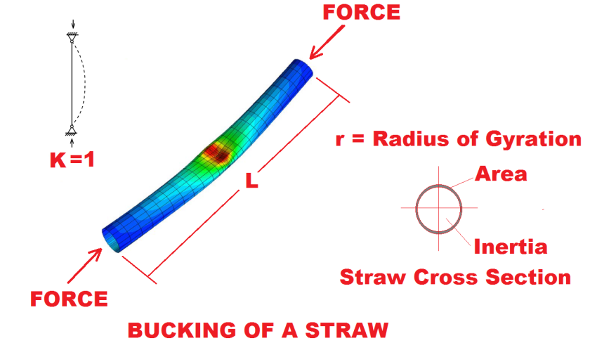
Have you never tried to compress a straw? When enough force is applied with your fingers to both ends of the straw, in some moment it will buckle. The KL/r factor is the main characteristic that defines the phenomena that govern the straw buckling when is compressed.
To understand what is KL/r, we need first to know what is K, L and r.
K represents the effective length coefficient, L is the unbraced length and r is the radius of gyration.
Each of this part of the equation KL/r have different ways to be calculated or determined. The important thing here is to understand what is the meaning of each one.
K Effective length coefficient
In theory, the effective length factor K for any column in a framed structure can be determined from a stability analysis of the entire structural analysis—eigenvalue analysis. Methods available for stability analysis include the slope-deflection method, three-moment equation method, and energy methods. In practice, however, such analysis are not practical, and simple models are often used to determine the effective length factors for framed columns. One such practical procedure that provides an approximate value of the elastic K-factor is the alignment chart method. This procedure has been adopted by the AISC, ACI 318, and AASHTO specifications, among others. At present, most engineers use the alignment chart method in lieu of an actual stability analysis.
K determination – Alignment Chart Method
The structural models employed for the determination of K-factor for framed columns in the alignment chart method are shown in the following figure.
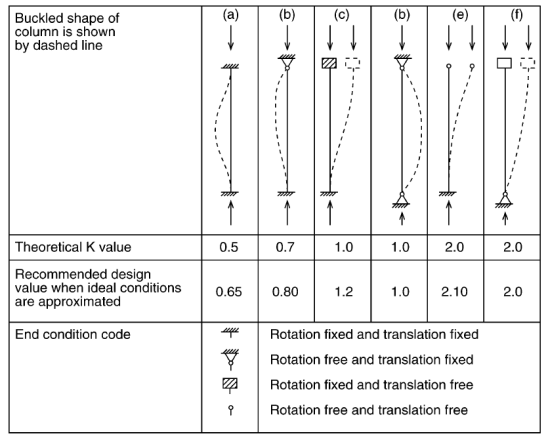
The assumptions used in these models are:
- All members have constant cross-section and behave elastically.
- Axial forces in the girders are negligible.
- All joints are rigid.
- For braced frames, the rotations at the near and far ends of the girders are equal in magnitude and opposite in direction (i.e., girders are bent in single curvature).
- For unbraced frames, the rotations at the near and far ends of the girders are equal in magnitude and direction (i.e., girders are bent in double curvature).
- The stiffness parameters, L=SQR(P/EI) of all columns are equal.
- All columns buckle simultaneously.
The member capacity for axial compression and for flexure is dependent on the spacing of elements which provide bracing along the length of a member.
r – Radius of Gyration
In structural engineering, the two-dimensional radius of gyration is used to describe the distribution of cross-sectional area in a column around its centroidal axis. The radius of gyration is given by the following formula:
r = SQR (I / A)
Where I is the second moment of area and A is the total cross-sectional area.
KL/r Calculation Example
Continuing with the straw example, let’s assume that it has an OD of 5 mm and ID of 4.8 mm, L = 200 mm and K factor = 1.
The cross-section Area A is 1.5439 mm^2.
A = 1.5439 mm^2
The second moment of area I is defined by the formula
I = 0.25 p (rOD^4 – rID^4)
Resolving:
I = (0.25) (3.1416) (2.5^4 – 2.4^4) = 4.62 mm^4
r = SQR (I / A) = SQR (4.62 mm4 / 1.5439 mm^2) = 1.73 mm
KL/r = (1) (200) / 1.73 = 115.59
What is the force that can produce buckling in the straw?
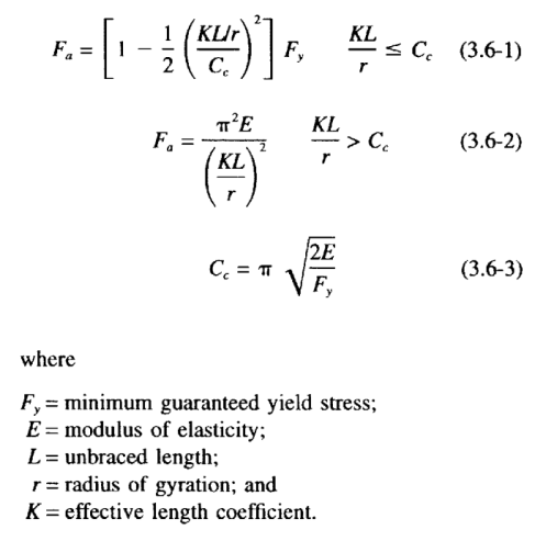
To resolve this question, we need first to define a Compression Stress Fa on the gross-section area. For the example, let’s use a ASCE standard that is very used by us in our tower design department. Using Chapter 3 of ASCE / SEI 10-15 standard defines Fa for axially loaded compression members as:
Let’s imagine that the straw is made of Polystyrene (PS) which modulus of elastic E is approximately 3.5 GPa and Yield Stress 4.17 ksi.
Summary of data in kgf, cm:
A = 1.5439 mm^2 = 0.01539 cm^2
Fy = 4.17 ksi = 293.18 kgf/cm^2
E = 3.5 GPa = 35690.07 kgf/cm^2
L = 200 mm = 20 cm
r = 1.73 mm = 0.173 cm
K = 1 = 1
Calculating Cc:
Cc = p SQR (2E/Fy)
Cc = (3.1416) SQR (2*35690.07 / 293.18)
Cc = 49.02
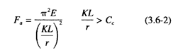
Due to KL/r = 115.59 > Cc = 49.02, formula 3.6-2 shall be used.
Fa = p2 * E / (KL/r)^2
Fa = (3.1416)2 * 35690.07 / (115.59) ^2
Fa = 26.39 kgf/cm^2
Which means the Compression Stress Fa that produces buckling on the straw.
The force F will be the amount of Force that needs to be applied to the straw until its failure due to buckling.
F = A * Fa = 0.01539 cm^2 * 26.39 kgf/cm^2
F = 0.41 kgf
Conclusion
All these calculations helped us to understand the importance of KL / r as an intrinsically related characteristic of buckling failure in a compressed member. In this case, a compression force of 0.4 kg (approx. 1 lb.) produces the failure of the straw. It is reasonable and very easy to demonstrate in the real world.
Next time when you attempt to compress a straw when drinking a refreshment, you’ll remember that KL / r factor is the responsible for its failure when you apply to much force.

Dear Sir,
You are awesome , I like your method of explaining things !
Please keep blogging such nice technical subject
LikeLiked by 1 person